All Works

Fabrication & robotics / UIUC · MakerLab / May 2026–present

Illinois MakerLab

I build robot systems and work with clients to turn their requirements into CAD revisions, prototypes, and print plans.

My contribution
3D Printing Engineer
Tools & methods
CAD, 3D printing, client coordination, print planning, LeRobot SO-101
Evidence
Assembled parts · CAD revisions · Print plans · Robot demonstration

At Illinois MakerLab, I work on both the parts and the planning behind them. I clarify what clients need, communicate proposed changes, and prepare designs and print jobs around the materials, hardware, and assembly involved.

For a reusable circuit-board mount, that meant revising supplied CAD and getting the client’s approval before a planned sample print. For a watch cleaner, I organized the part library into 13 print configurations with material and machine-time estimates.

Alongside these projects, I built and trained LeRobot SO-101 arms. The examples below show my work in CAD, printing, assembly, software, and client coordination.

LeRobot SO-101

Building and training
the robot arms.

I handled the printing, mechanical assembly, wiring, calibration, software setup, teleoperation, and training. This meant bringing the hardware and software together before teaching the arm a task.

The video shows the trained arm performing tasks. The robot platform is LeRobot’s design; the build and setup shown here were my work.

21-second silent video · Playback controls included

Download the clip ↓
The trained arm performs tasks after fabrication, assembly, calibration, software setup, and training.

Print trials & assembly

Functional Hand

Printing and assembling an existing assistive grip design.

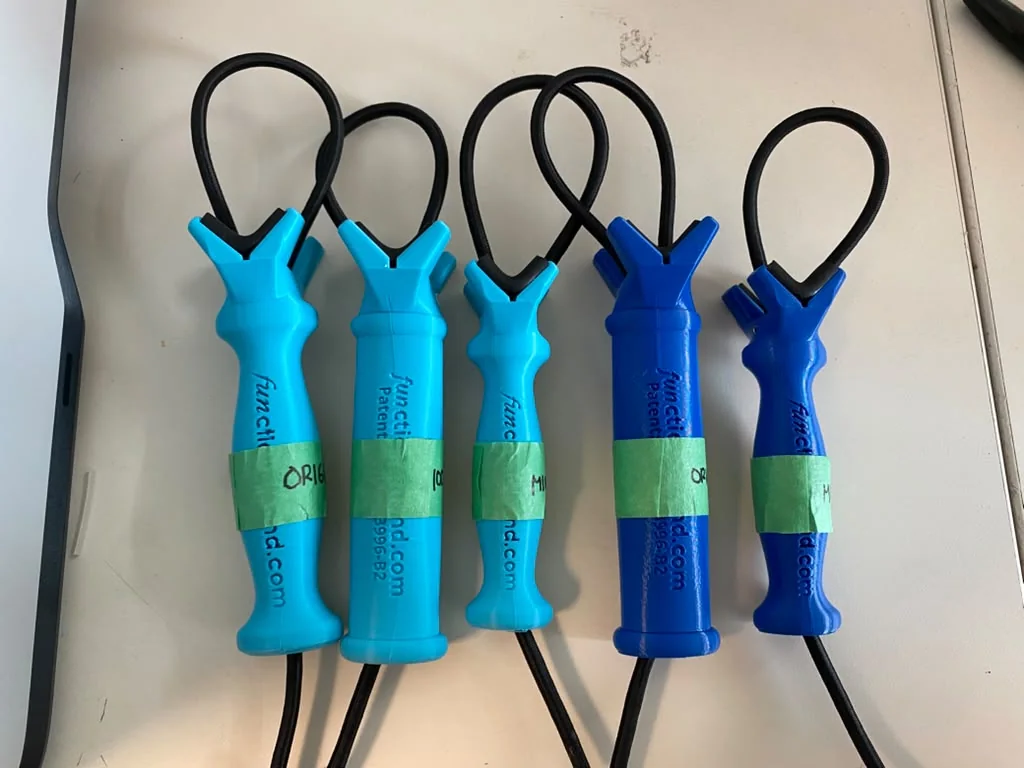
I printed and assembled grips from the Functional Hand design, which uses a printed body and flexible loops to hold objects. My work covered the physical parts and assembly; the device design belongs to Functional Hand.

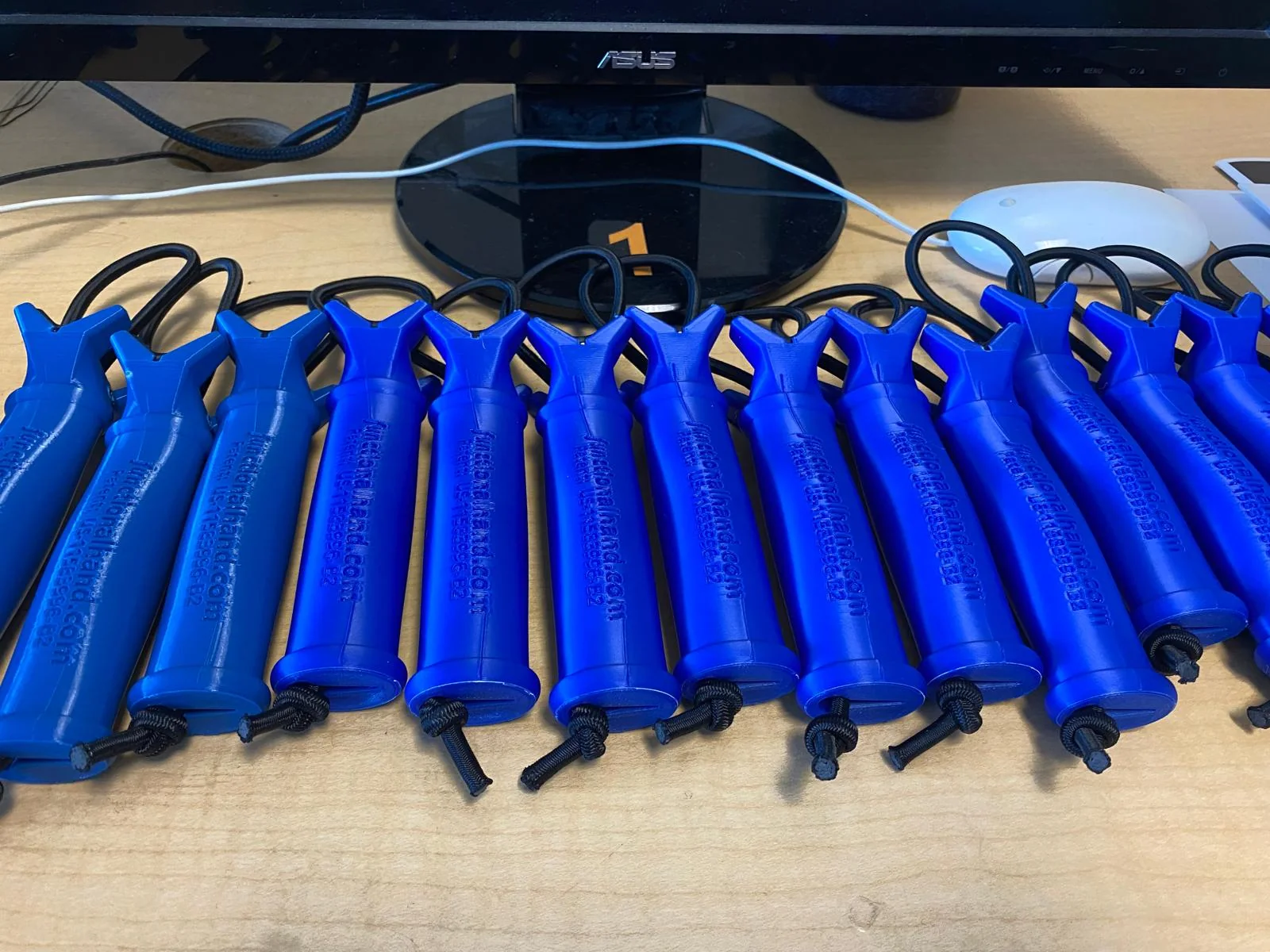
The work included failed prints and test pieces as well as assembled grips. The photos show that progression and the batch of completed assemblies.

Device design: Functional Hand. The work shown here concerns printing and assembly.
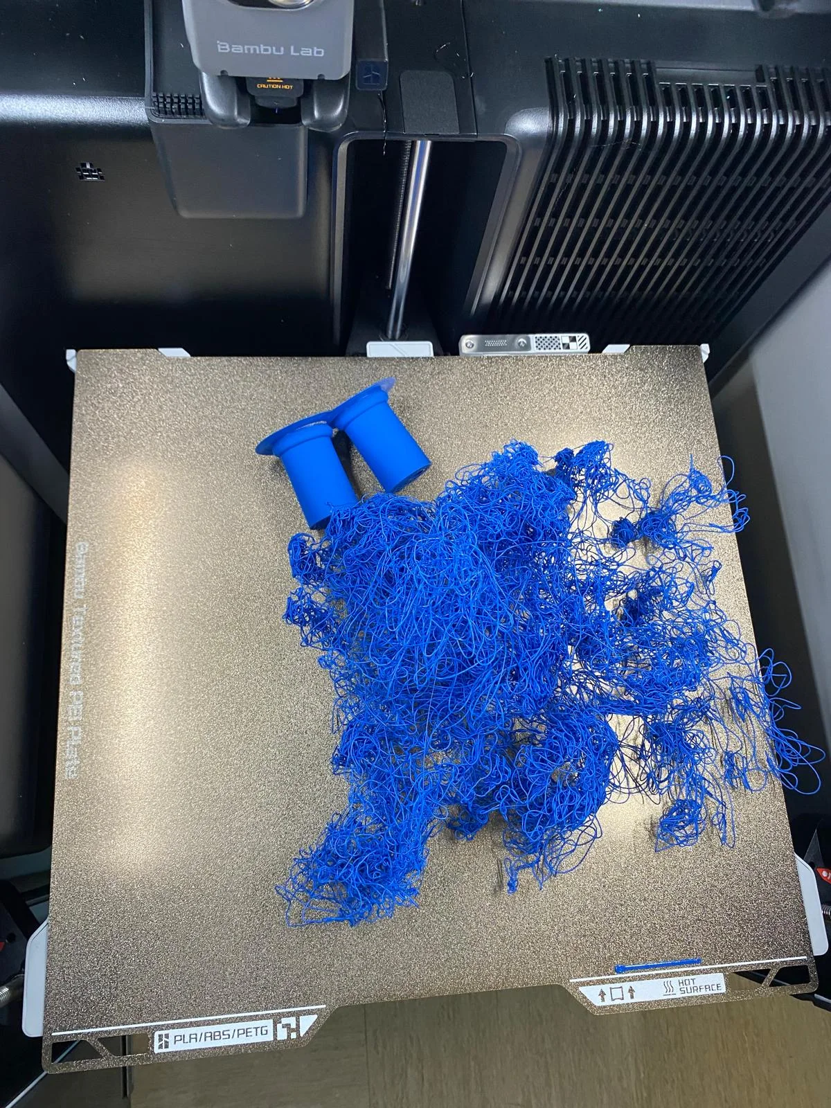
Failed blue Functional Hand print with loose filament on the build plate
An unsuccessful print

Loose filament and incomplete parts on the build plate during the print trials.

Five assembled blue and turquoise Functional Hand grips with flexible loops
Assembled grips

Printed bodies fitted with flexible loops.

Batch of completed blue Functional Hand grips on a worktable
The completed assemblies

A batch of assembled Functional Hand grips on the MakerLab worktable.

CAD revisions & physical prototypes

Tissue-clamp prototyping

Revising a small assembly with several moving interfaces.

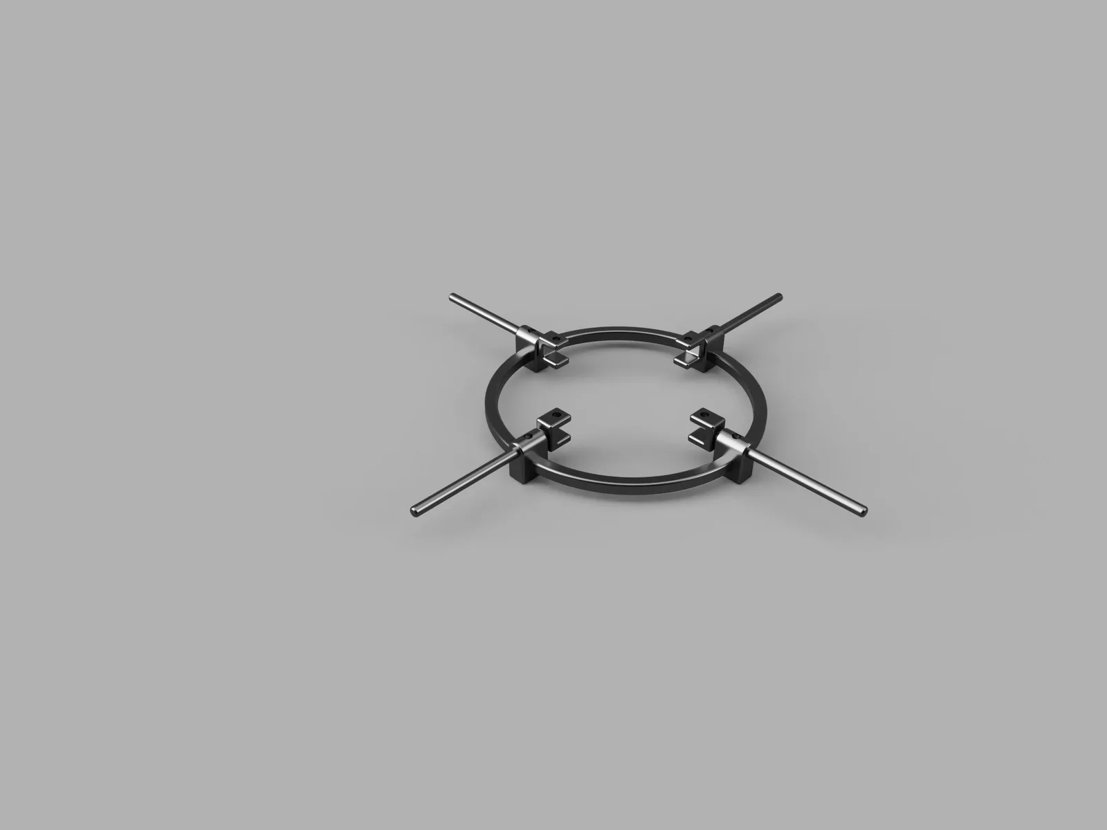
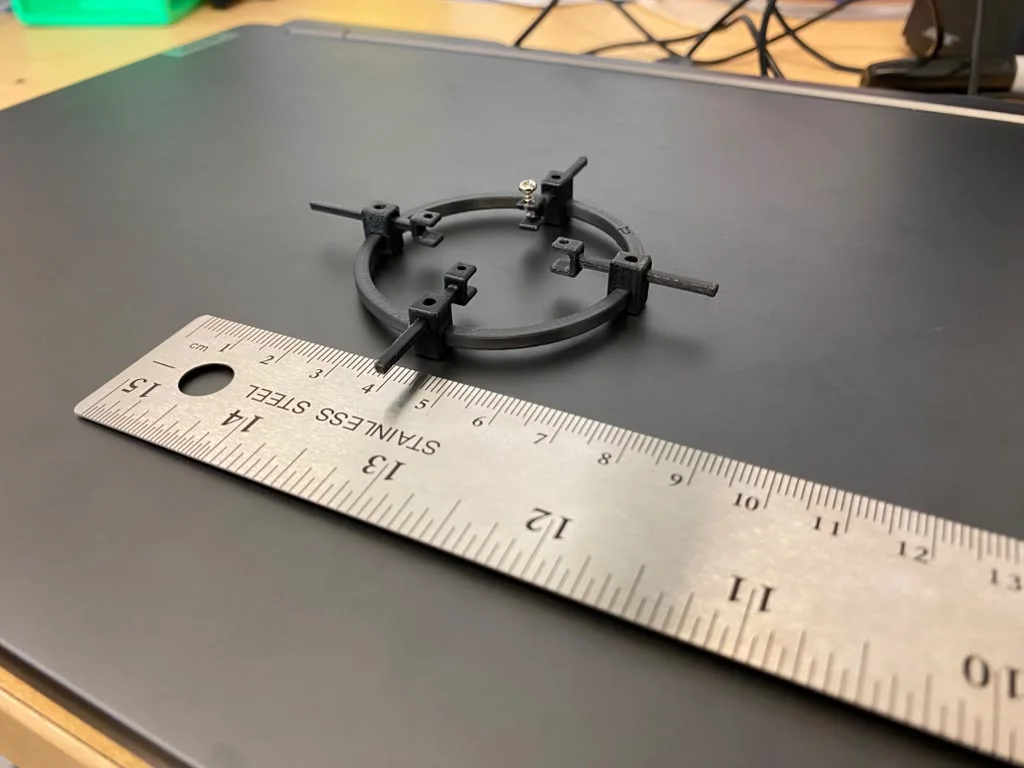
I worked on CAD revisions and printed prototypes of a tissue clamp. Its frame, rods, sliders, and screws had to fit together in a compact assembly, so the connections mattered as much as the overall shape.

The prototype and revision notes helped define the next changes: thicker slides, larger screws, thicker connections, and fewer fasteners underneath. The photos show the CAD and a physical prototype. Clamping performance has not yet been measured.

CAD view of a circular tissue-clamp assembly with four rods and sliding clamps
The clamp assembly in CAD

The frame, rods, sliding clamps, and screws shown together before printing.

Black printed tissue-clamp prototype beside a ruler
A physical prototype

The printed assembly beside a ruler. Revision notes address the slides, fasteners, and connections.

Client requirements & CAD adaptation

Reusable PCB mounts

A mounting change driven by how the client uses the board.

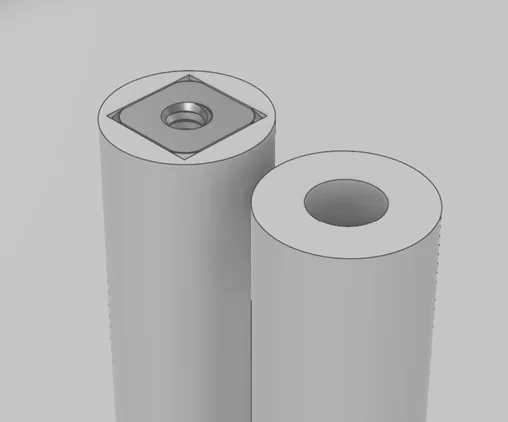
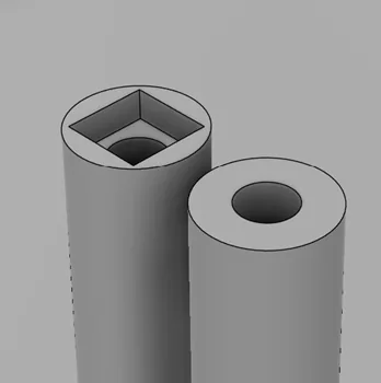
The client needed to remove circuit boards for debugging and reinstall them. I adapted the supplied kit CAD with pockets that hold square nuts, matching the existing 4-40 hardware so the board could use a reusable fastening arrangement.

I sent the revised geometry and an assembly view with the nut in place to explain the change. The client approved the direction. I then planned a sample print to check nut fit, tolerances, and support around the overhang before production.

Base kit designs supplied by the client. My contribution was the mounting adaptation, print preparation, and coordination of the proposed changes.

Revised CAD mounting feature with a square nut assembled in its pocket
The nut in place

The revised CAD assembly shows how the existing 4-40 square nut sits in its pocket.

Revised CAD mounting feature showing the empty square-nut pocket
The revised pocket

The same feature without the nut. A sample print was planned to check fit and the overhang.

Print preparation & job planning

Watch-cleaner production planning

Organizing a part library into a practical print plan.

I prepared the supplied UberKiwi watch-cleaner parts as 13 print configurations. I grouped them by color, PLA or PETG, infill, and support requirements because different parts needed different print settings.

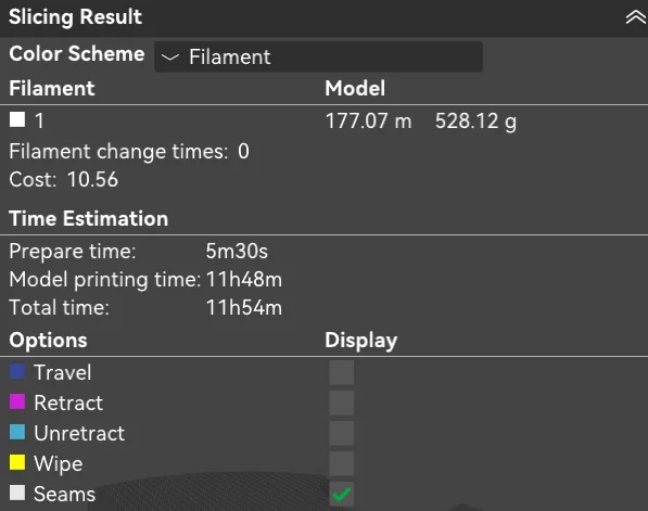
The slicer estimates gave the job a material and machine-time plan before printing. This example shows my production preparation; the estimated times do not represent measured turnaround or completed delivery.

UberKiwi machine design and manual: Frank Simons. The contribution shown here is print preparation and production planning.

Print configurations in the watch-cleaner plan
13
Materials separated into appropriate jobs
PLA + PETG
Watch-cleaner slicing result showing estimated filament use and print duration
Planning a print job

The slicer estimates filament use and print duration for one watch-cleaner configuration.

Project documentation

The photographs, CAD views, print records, and robot video show the work described above. Print times and material quantities shown in slicer records are estimates. The robot video is a task demonstration; task success was not measured across repeated trials.

Next project

Tape Spring Hinge