Deployable structures / UIUC · AE 498 / 2026
Bistable Composite Boom
I built a carbon-fiber boom that stays coiled or extended, then used measurements to check the model behind it.
Overview
Two stable shapes in one thin structure.
A deployable boom needs to pack away compactly and hold a useful shape when extended. I modeled, fabricated, and measured a thin carbon-fiber specimen that could stay in either configuration without being held.
The measurements of how tightly each shape curved were within about 5% of the model’s predictions for this specimen. I then screened 5,476 simulated layer arrangements to explore alternatives.
That comparison showed a useful tradeoff: lowering the estimated energy needed to switch shapes also changed the coiled geometry. A design needed to meet both requirements. The alternative arrangements remained simulations.
From laminate model to specimen
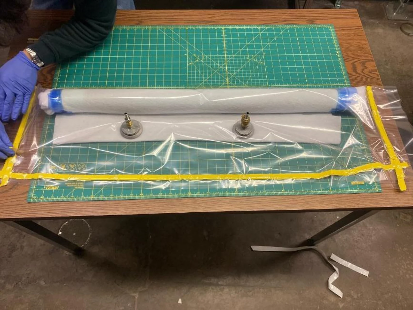
I used MATLAB to model a three-layer composite, then fabricated it on the available mold. Layer arrangement matters because it determines the shapes the thin structure can hold. Building a baseline gave me a real part to compare with the prediction.
Measuring both shapes
I measured the extended and coiled configurations with stereo cameras. Their curvatures were within about 5% of the predicted values. I also adjusted model parameters to explore the remaining mismatch; fitting those same measurements was a calibration step, rather than a separate test of the model.
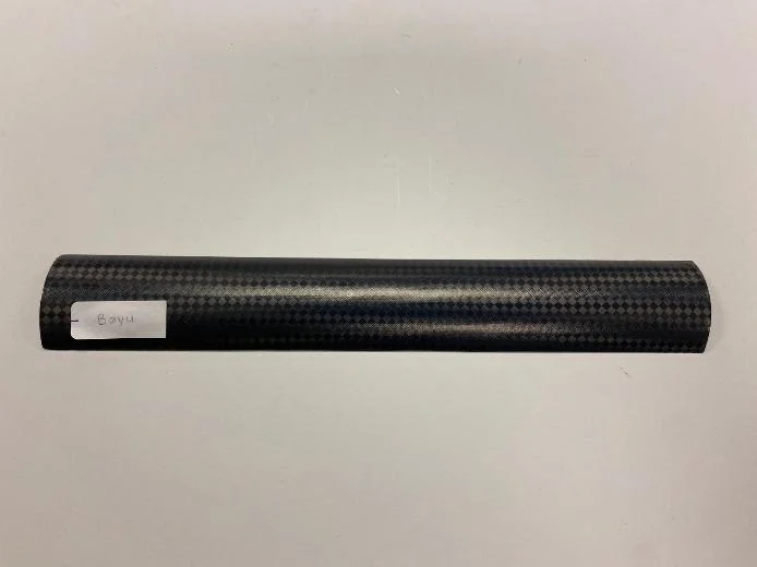
The fabricated baseline specimen holds its extended configuration.
Project report, PDF page 8.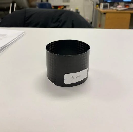
The same specimen also holds a coiled configuration.
Project report, PDF page 8.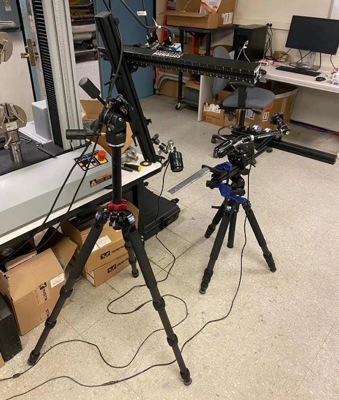
Stereo cameras recorded the specimen geometry for comparison with the model.
Project report, PDF page 9.Choosing what to optimize
I compared 5,476 modeled layer arrangements. Some lowered the estimated energy required to move between the two stable shapes, but they also changed the stored shape. The screen helped identify which candidates deserved closer study without treating the lowest energy as the only design objective.
Go deeper / Full technical report
Ultrathin Bistable Composite Short Boom
Open the original report for the methodology, calculations, and detailed results behind this overview.